
How to Crimp Automotive Electrical Connectors Correctly
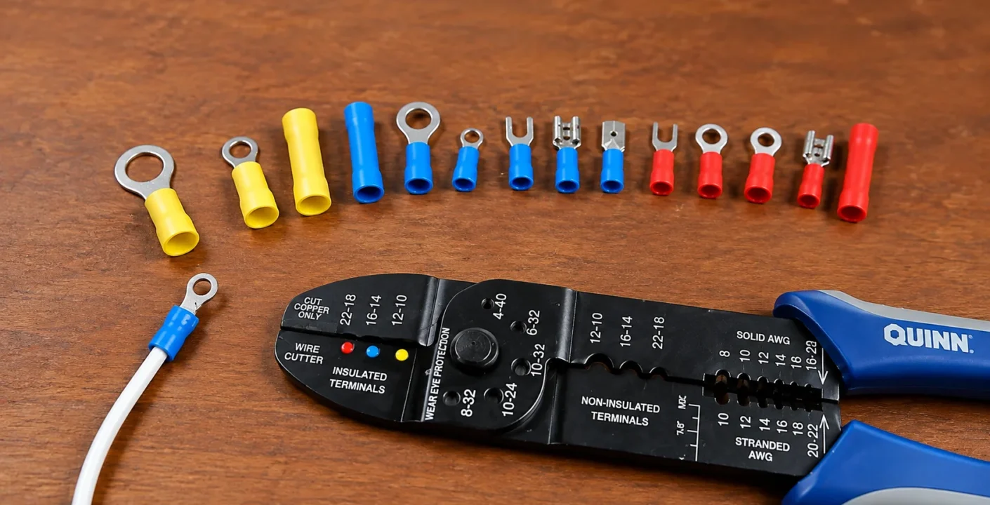
Automotive connector crimping creates a secure electrical connection by mechanically compressing a terminal around a conductor. Poor crimping can introduce resistance, cause intermittent faults and allow wires to separate under vibration.
A reliable crimp depends on using a compatible terminal, wire and crimping tool. Wire preparation, terminal positioning, crimping and inspection also need to be completed carefully.
This guide explains how to select, crimp, inspect and test common automotive electrical connectors for vehicle, trailer, caravan and machinery wiring.
What Is an Automotive Crimp Connection?
Automotive connector crimping joins a metal terminal to a stripped section of stranded wire. Pressure from the crimping tool deforms the terminal around the conductor strands to create a firm joint.
A completed crimp should provide:
- Low electrical resistance
- Reliable current flow
- Mechanical strength
- Resistance to vibration
- Support for the wire insulation
- Protection against accidental separation
Automotive wiring may be exposed to vibration, movement, temperature changes, moisture and contaminants, so each terminal connection needs to be formed correctly.
Common Types of Automotive Crimp Terminals
Automotive connector crimping techniques vary by terminal type. Common automotive electrical terminals include ring, fork, blade, butt and open-barrel terminals, along with larger battery lugs.
| Terminal type | Common applications | Key consideration |
| Ring terminals | Battery, earth, starter, alternator and accessory connections | Match the ring opening to the stud size |
| Spade and fork terminals | Terminal blocks and equipment connections | Secure the fastener correctly |
| Blade terminals | Switches, relays, speakers and accessories | Match blade dimensions and current ratings |
| Butt connectors | Repairs, circuit extensions and accessory installations | Each wire requires its own crimp |
| Open-barrel terminals | Automotive connector housings | Use a compatible open-barrel crimping tool |
| Battery lugs | Battery, winch, starter and inverter connections | Match the lug and crimping equipment to the conductor size and application |
Ring Terminals
Ring terminals have a circular opening that fits over a stud or bolt. They are commonly used for battery, earth, starter, alternator and accessory connections.
The ring opening should closely match the stud size. An oversized opening can reduce the available contact area or allow the terminal to move.
Spade and Fork Terminals
Fork terminals slide underneath a screw or threaded fastener without requiring the fastener to be fully removed.
They are useful for accessible terminal blocks and equipment connections. Secure the fastener properly so vibration cannot loosen the terminal.
Blade and Quick-Disconnect Terminals
Blade terminals create removable electrical connections. They are commonly found on switches, relays, speakers and accessory circuits.
Male and female terminals must have matching blade dimensions and current ratings.
Butt Connectors
Butt connectors join two wire ends. Each wire enters one side of the connector and receives a separate crimp.
They are commonly used for repairs, circuit extensions and accessory installations. Heat-shrink butt connectors can provide additional environmental protection when installed correctly.
Open-Barrel Terminals
Open-barrel terminals are frequently used inside automotive connector housings. They usually include:
- Conductor wings that grip the bare wire
- Insulation wings that support the insulated section
- A locking feature that holds the terminal inside the housing
These terminals require a compatible open-barrel crimping tool and careful positioning.
Battery Lugs
Battery lugs are designed for larger cable sizes and high-current circuits. They may require heavy-duty manual, hydraulic or powered crimping equipment.
Battery, winch, starter and inverter connections should use lugs and tools matched to the conductor size and application.
Tools and Materials Needed
Automotive connector crimping starts with having compatible tools and components ready before making the connection.
You may need:
- Automotive wire
- Compatible crimp terminal
- Ratchet or terminal-specific crimping tool
- Wire stripper
- Wire cutter
- Heat-shrink tubing where required
- Heat gun
- Multimeter
- Connector housing where applicable
Pliers and side cutters do not create a controlled crimp profile. They can flatten the terminal unevenly, damage the insulation or leave space around the conductor.
A ratchet crimping tool applies controlled pressure and usually prevents the jaws from releasing until the crimping cycle is complete. KP Automotive supplies products such as the Narva Tradesmen Crimping Tool for suitable automotive terminal applications.
Step 1: Disconnect the Power Supply
Automotive connector crimping should begin with the battery disconnected or the relevant circuit isolated.
Some vehicles require specific procedures before battery disconnection because radios, security systems, electronic modules and battery-management systems may lose stored settings. Check the vehicle manufacturer’s instructions first.
Keep the disconnected cable away from the battery terminal while completing the work.
Step 2: Select the Correct Terminal
Automotive connector crimping depends on matching the terminal to the wire, circuit and application.
Check:
- The conductor area in mm² or AWG
- The terminal-stud or blade size
- The circuit current
- The connector housing
- The installation environment
- The crimping tool profile
An oversized terminal may not compress tightly around the wire. An undersized terminal may damage the conductor, prevent full insertion or split during crimping.
Insulated terminals are often colour-coded according to wire-size ranges. Check the manufacturer’s specifications because colour systems can vary between product ranges.
For open-barrel connectors, confirm that the terminal belongs to the exact connector series. Similar-looking terminals may differ in width, locking design, plating or supported wire size.
Step 3: Cut the Wire Cleanly
Use a sharp wire cutter to make a square, clean cut.
A crushed or angled wire end can make insertion difficult and cause conductor strands to fold back. If the wire is corroded, blackened or damaged, cut it back until clean copper is visible.
Inspect older wiring carefully. Corrosion can travel underneath the insulation and may extend beyond the visible connection.
Step 4: Strip the Correct Length of Insulation
Use a wire stripper matched to the conductor size. Remove enough insulation for the conductor to sit fully inside the terminal’s conductor barrel.
The stripped section should generally reach the end of the conductor barrel without extending too far into the terminal or connector.
Avoid:
- Cutting conductor strands
- Twisting strands excessively
- Leaving too much bare copper exposed
- Placing insulation inside the conductor-crimp area
- Stretching or thinning the insulation
Damaged strands reduce the effective conductor area and can weaken the connection. If several strands are cut, trim the wire and strip it again.
For open-barrel terminals, the bare conductor sits within the smaller conductor wings. The larger rear wings close around the insulation to provide strain relief.
Step 5: Position the Terminal in the Crimping Tool
Place the terminal in the correct crimping die.
Many insulated terminals use colour-coded die positions. Open-barrel terminals require a die shaped to fold the terminal wings inward around the conductor and insulation.
Confirm that:
- The terminal faces the correct direction
- The conductor barrel aligns with the correct die
- The insulation support sits in its intended crimping area
- The terminal’s locking tab remains undamaged
- The terminal is held securely in the tool
Close the tool slightly to hold the terminal in position while leaving enough room to insert the wire.
Step 6: Insert the Wire Fully
Insert the stripped conductor into the terminal until the wire reaches the correct position.
Check that:
- All conductor strands enter the barrel
- No strands remain outside the terminal
- Bare copper fills the conductor-crimp section
- The insulation reaches the insulation support
- The conductor does not extend into a mating or locking area
Some terminals include an inspection opening that allows the conductor position to be checked before and after crimping.
Step 7: Complete the Crimp
Keep the wire and terminal steady, then close the handles through the full crimping cycle.
A ratchet tool should release after the required compression has been applied. Avoid repositioning the terminal midway through the crimp.
Open-barrel terminals may use one operation for both sets of wings or separate operations for the conductor and insulation sections, depending on the tool.
Use the terminal manufacturer’s specified tool, die and process for sealed connectors, high-current terminals and production harness work.
Step 8: Inspect the Connection
Inspect every completed crimp before placing it into service.
A sound crimp should have:
For open-barrel terminals, the conductor wings should fold evenly into the wire strands. The insulation wings should support the cable without cutting through its insulation.
Replace visibly uneven or damaged terminals.
Inspection and testing are recognised parts of automotive electrical repair practice. Australian Government automotive training requirements for diagnosing and repairing automotive electrical systems include checking terminal retention and diagnosing faults such as high resistance and damaged connectors or wiring.
Step 9: Perform a Pull Test
Hold the terminal and pull the wire firmly using controlled hand pressure.
The wire should remain secure without slipping, rotating excessively or separating from the terminal. A pull test can identify an incorrectly sized terminal, incomplete crimp or poorly positioned conductor.
Avoid pulling directly on connector housings, seals or delicate locking tabs.
Commercial harness manufacturing may use calibrated pull-force testing. For workshop and DIY installations, a firm manual test provides a useful basic check.
Step 10: Seal and Protect the Connection
Connections exposed to water, dirt, salt or engine-bay contaminants may require additional protection.
Suitable options may include:
- Adhesive-lined heat-shrink tubing
- Heat-shrink crimp terminals
- Sealed connector housings
- Wire seals
- Split conduit
- Braided sleeving
- Harness tape
- Rubber grommets
- Strain-relief clamps
Position heat-shrink tubing on the wire before crimping where the terminal design requires it. Centre the tubing over the completed joint and apply heat evenly with a heat gun.
Open flames can overheat the insulation, damage the terminal or ignite nearby materials.
Step 11: Insert Terminals Into the Connector Housing
For multi-pin automotive connectors, align the terminal correctly before inserting it into the housing.
Push the terminal into its cavity until the locking feature clicks into place. Pull gently on the wire to confirm that the terminal is retained.
Check:
- Pin location
- Wire colour
- Terminal orientation
- Seal position
- Secondary-lock position
- Connector polarity
A terminal inserted into the wrong cavity may require a dedicated removal tool. Screwdrivers and improvised picks can damage the housing or locking mechanism.
Step 12: Reconnect and Test the Circuit
Reconnect the battery or restore power after all wiring has been secured and insulated.
Test the circuit under normal operating load. A multimeter can be used to check:
- Supply voltage
- Continuity
- Polarity
- Earth quality
- Voltage drop
- Current draw
A continuity test alone may not identify a high-resistance connection. Voltage-drop testing with the circuit operating provides a more useful assessment of connection performance.
Should Automotive Crimps Be Soldered?
A correctly formed crimp is designed to provide the mechanical and electrical connection on its own.
Adding solder can make the wire rigid near the terminal. Vehicle movement and vibration may then concentrate stress where the solder ends. Solder can also flow into areas intended to remain flexible or interfere with connector assembly.
Follow the terminal and equipment manufacturer’s installation method. If a connector is designed for crimping, use the correct terminal and crimp profile.
Common Automotive Connector Crimping Mistakes
Even a crimp that looks secure can fail if the terminal, wire or tool is mismatched. Check for these common problems.
Using the Wrong Crimping Tool
A mismatched die can leave the terminal loose or deform it. Use a tool and die designed for the terminal type and supported wire size.
Choosing the Wrong Terminal Size
A terminal that is too large may not grip the conductor securely. One that is too small can prevent full insertion, damage strands or split during crimping.
Check the specified mm² or AWG range rather than relying on insulation colour alone.
Stripping the Wire Incorrectly
Too much exposed copper increases the risk of accidental contact and corrosion. Too little can leave insulation inside the conductor crimp.
Strip only enough insulation for the conductor to fill its intended crimping area.
Damaging Conductor Strands
Cut or missing strands reduce the effective conductor area and can weaken the connection. If the stripper damages several strands, cut the wire back and strip it again.
Leaving the Cable Unsupported
Long or heavy cables can place stress on the terminal. Support the harness close to the connection while allowing enough movement for servicing.
Reusing Crimp Terminals
A terminal that has already been crimped cannot usually be restored to its original shape or performance. Replace removed or damaged terminals with new components.
Crimping Corroded Wire
A new terminal will not correct damaged conductor strands. Cut the cable back to clean copper or replace the affected section.
How to Check a Suspected Bad Crimp
A poor connection may show physical or electrical symptoms.
Look for:
- Intermittent accessory operation
- Flickering lights
- Unusual heat near a connector
- Discoloured insulation
- Melted connector housings
- Voltage loss under load
- A terminal that moves inside its housing
- A wire that pulls out easily
- Visible corrosion around the terminal
Inspect the wire, terminal, housing and mating connector. Measure voltage drop while the component is operating.
Replace heat-damaged or corroded parts and identify the source of excess current or resistance.
Choosing Connectors and Crimp Terminals
Automotive connector crimping is only reliable when the connector and terminal suit the application.
Select automotive connectors according to:
- Wire size
- Maximum circuit current
- Number of circuits
- Required environmental protection
- Operating temperature
- Installation location
- Connection frequency
- Vehicle or equipment compatibility
Sealed connectors are suited to areas exposed to water, mud or dust. Insulated blade, ring and butt terminals can suit protected accessory installations. High-current circuits require terminals and cables specifically rated for the expected load.
KP Automotive supplies automotive electrical products, including connectors, terminals, wiring accessories and crimping tools for vehicle, transport, agricultural and workshop applications.
A Reliable Crimp Starts With Compatible Components
Automotive connector crimping starts with matching the wire, terminal and tool. Clean conductor strands, accurate stripping, correct positioning and full tool compression help create a strong and consistent connection.
Inspect and test each terminal before completing the installation. For high-current circuits, safety-critical wiring or complex vehicle electronics, arrange installation through a qualified auto electrician.